Training Schedule
Training for Infrared and EMT professionals world-wide.

A RIC, “Rotor Influence Check” is one of the test methods utilized for de-energized motor testing. It is commonly used for baseline testing but can also be used to confirm or correlate some anomalous test results. It also works well for troubleshooting when a motor cannot be run. It should also be applied for motor acceptance as a quality assurance validation. The RIC test can be performed on all three-phase induction motors including synchronous motors and wound rotor motors.
It can be a tedious and time-consuming endeavor. It involves precise stepping of the rotor to acquire measurements. This generally requires removal of the coupling guard and sometimes, depending on the driven component, uncoupling. On very large motors, due to the rotor mass, a strap wrench and a pipe for leverage may be necessary to precisely position the rotor. It is a test you love to hate or hate to love! At times it may be the only test available short of motor removal and delivery to a motor shop.
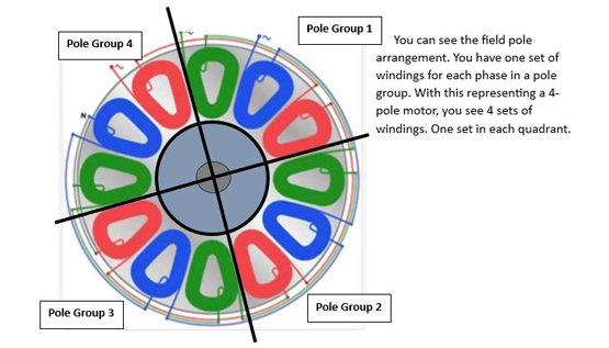
A RIC is performed by rotating the rotor in increments around a 360-degree rotation. Usually, the arc of a pole group should suffice with a full rotation test, this is not uncommon. The test measurement increments are determined by the number of motor field poles. Using nameplate RPM, say for example 1780, round that up to 1800 which is synchronous RPM. Divide 7200 by 1800 and that will equal the number of pole groups, in this case 4. (7200/1800 = 4) Divide 360, full rotation, by 4 and that will provide the arc of one set of coils for each phase, see Figure 2. (360/4 = 90) To achieve an optimal resolution each pole group will have 18 tests taken over that arc. In the case of a 4 pole motor, the arc of a pole group is 90 degrees. Given 18 tests required, 90 divided by 18 equals 5. (90/18 =5) The rotor is stepped in 5-degree increments. Inductance measurements are taken at each increment and a plot is generated showing those results. The test signal that is utilized is a low voltage of approximately 5VAC at a frequency of 1200HZ. What is being measured is the effect of the residual magnetic fields in the rotor and its effect on the measured stator inductance. Hence, the name “Rotor Influence Check.” Most new motors are test run before shipment, so often there is still enough residual magnetism to produce a pattern on a motor that has been received.
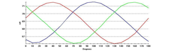
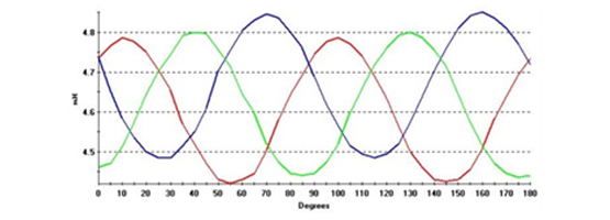
Depending upon the type of motor, a RIC can provide two distinct patterns. The most common for low voltage, cast aluminum rotors is the type displayed in Figure 1 and 3.
Figure 1 is a lap wound stator and Figure 3 is concentric wound. These are the patterns most motor testing analysts expect to see when they perform a RIC test. These are what are referred to as a rotor with influence. This is a common pattern for random wound cast aluminum rotor motors. Because there are so many of these in service in various sizes, this is why it’s a pattern often seen.
However, when conducting RIC tests on some medium and all high voltage motors you might see a pattern like the one below. This is a pattern for a low influence rotor. Motors that utilize copper barred rotors tend to have minimal residual magnetism. This is because of a much higher level of quality with the motor construction. Copper rotor bars, form wound stator coils and precision machining results in little rotor influence.
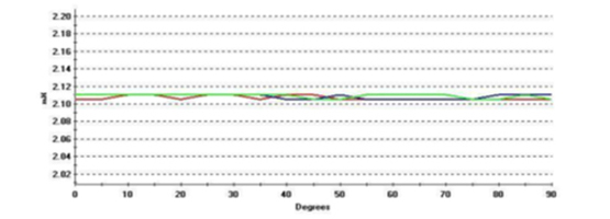
Motors with a large air gap between the rotor and stator, old U frame motors, will typically have this kind of plot. This is caused because of the wider air gap. Magnetic field strength will vary as the inverse of the square of the distance. Wider air gap the less influence.
A Rotor Influence Check can provide data to identify many motor anomalies. Consider taking one of our motor certification courses. We discuss the RIC test in considerable detail. Also inquire about our Motor Data Analysis Wall Charts.


