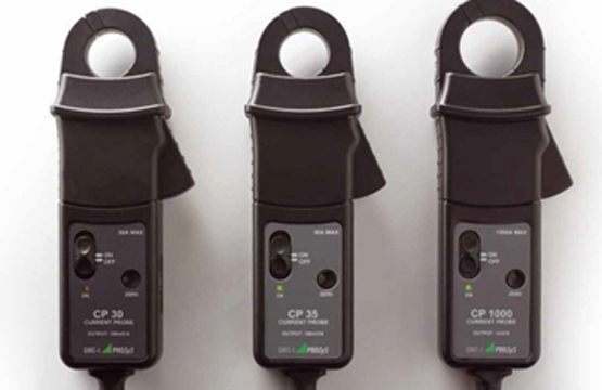

When performing energized electric motor testing on medium and high voltage systems, it is necessary to acquire data from potential and current transformers. PT’s and CT’s step down the line currents and voltage to much safer levels. To connect to these circuits, we need to know the step-down ratio. Voltage is a simple division answer, simply divide a 1:1 PT ratio value into the known line voltage; For example; 4160 / 120 = 34.66 or 35:1. Current transformers are not necessarily so easy.
There are essentially four methods to determine CT ratios, one of those requires the circuit be de-energized.
Amp or current probes are used for current acquisition during energized testing. They are also current transformers. Through electromagnetic induction or transformation action, circuit current is induced through the jaws of the current or amp probes that clamp around the primary conductors. Generally motor testing software’s default the acquisition ratio as 1:1.
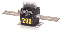
The CTs installed in the motor circuit have a designed stepdown ratio to reduce the secondary current to safer levels. Knowing the exact ratio is essential in successful monitoring of the motor under test. Misdiagnosing current, particularly underestimating current, could allow an overload condition to exist which could result in a catastrophic failure.
The CT in Figure 2 has a 200:5 or 4:1 ratio. If the circuit is accessed when de-energized, you can look at one of the installed CTs and find the ratio on the unit. If the circuit is energized, we must pursue other methods.
When analog ammeters are installed, we can easily determine the CT ratio by observing the meter full scale value and then divide that value by 5.
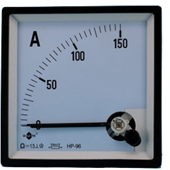
The meter in Figure 3 has a full scale of 150 amps. Divide 150 by 5 and the ratio will be 30:1. With more and more circuits utilizing digital instrumentation this method is becoming a thing of the past.
When we are dealing with digital equipment’s, we must conduct more research to determine the proper CT ratio. These units are set up initially by technicians upon installation. It is essential that the correct ratio is verified.
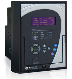
We can use a similar method like we discussed earlier for determining PT ratios. Collect a current data set at a 1:1 ratio and divide the acquired reading into the meter reading. Simple, but-not necessarily accurate. If the unit is not set up properly it could be indicating incorrect readings. The best way to prevent this is to research prints, if they are available.
If prints are available, look at the motor portion of the secondary circuitry.
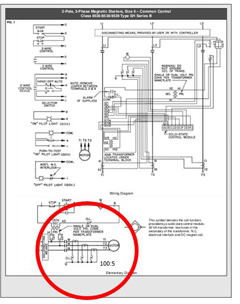
Find the CTs in the schematic and look for a ratio in proximity to the CTs. These drawing show a 100:5 which will be a 20:1 ratio.
For more information on Control Transformers and electric motor testing, contact the Snell Group and schedule one of our comprehensive training courses. Don’t forget to ask about our new De-Energized and Energized Electric Motor Data Analysis Wall Charts. A 36” x 48” laminated chart that is a wealth of information. Also look for the release of Our Energized Electric Motor Data Analysis Wall Chart.