
Probably the most common question we get asked during training, especially in a building applications class, is “What emissivity setting should I use?” Why this happens is actually not very surprising as long as the manufacturers insist on putting easily searchable emissivity tables in the menu system of many infrared cameras or continue marketing equipment as “easy point and shoot” systems, these questions will certainly keep coming. Thermographers seem to gravitate toward this particular menu item like moths to a porch light. This, even though much of the time changing or adjusting the emissivity setting is not something we typically need to do in building applications.
Most of the work with infrared in building inspections is qualitative (i.e. finding hot or cold spots). You only need to set emissivity, and background/reflected temperature values for that matter when you are attempting to measure an absolute temperature on a surface. Doing so does not help with the qualitative aspects of the image. Even then, when trying to measure temperature, there are still many variables that will affect your ability to accurately accomplish this. Most building surfaces have high emissivity. Even windows have a relatively high emissivity but may be confusing because of their specular nature. Consider what the image is already telling you about the situation. Building inspections utilizing infrared cameras should be considered an imaging science not a measurement science in most situations.

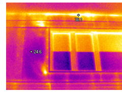
For example, in the thermal image on the right you will notice two spot markers on the exterior wall showing apparent temperatures at those locations. One obviously appears to be warmer than the other; however, we also see a very interesting qualitative pattern (i.e. concentrated, irregular sized, hot spots) above the window near the soffit which appears to be warm air exfiltrating from the building. Additionally, there is a smaller, more concentrated area of apparent air leakage seen near the lower-left corner of the window. These are the important data points here, not that the wall happens to be 36°F in one spot and 24°F in the other.

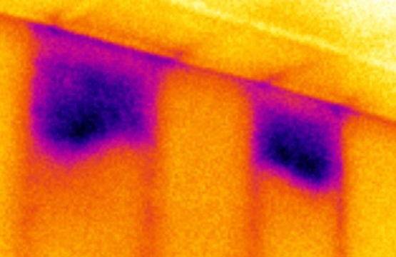
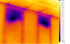
In another example, we see areas of apparent missing insulation from the interior without the aid of any temperature points, just the color scale where brighter indicates warmer and darker cooler. Of course, understanding the environmental conditions which are creating these patterns is important. In this case, it was a cold-weather situation, about 10°F outside. Putting spot temperatures on the image would add nothing of value here and would distract from the more important data point which is that we have located two apparent insulation voids.
So which emissivity setting should you enter? 0.95, the value you are going to use when conducting a camera functionality check to see if your imager is operating properly prior to an inspection.
What is a functionality check? Learn more here.
We set it to .98 when measuring the temperature of a person’s tear duct because that is the emissivity of skin. If you are a Level I building thermographer leave it there. You do not have to set it to the value of “paint”, “wood” or “concrete” to look at those surfaces with an infrared camera. You just look at those surfaces for qualitative patterns as seen in the examples above.
Most importantly, though, is that a new thermographer, or Level I for that matter, may not be qualified to measure temperatures, without a written procedure, with a thermal imager other than that of a tear duct and possibly electrical tape (which is .95). You may need to adjust for the proper background temperature. There is a lot going on with physics that really requires a Level II proficiency before attempting spot temperature measurements.
So, for now, leave emissivity at .95 and look for qualitative differences (i.e. thermal patterns) of air leakage and missing insulation, not the temperature values. It is about locating thermal anomalies on building surfaces (what these cameras do best) and for which you do not need an emissivity table.