Training Schedule
Training for Infrared and EMT professionals world-wide.


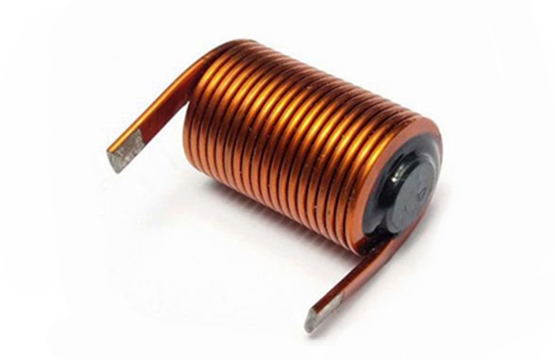
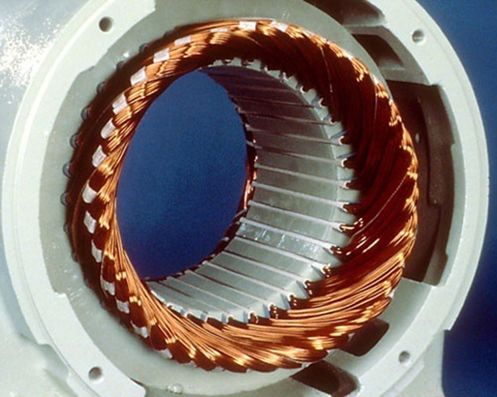
De-energized Electric Motor Testing (EMT) equipment provides a suite of varying tests. Of all the differing tests, inductance is of utmost importance because it is affected by everything in the motor. From a review of the below formula, you can see that inductance measurement is comprised of a number of factors, the characteristics of the core material, the dimension of the core, and the wire or windings, i.e. number of turns, all affect the measured inductance. The position of the rotor in relation to the center bore of the stator will affect the magnetic field generated by test measurements, which will impact the measured inductance.

L = Inductance
π = 3.14
μ = Permeability (Core Material)
A = Cross-Sectional Area of the Core
N = Number of turns
Inductance quite simply is opposition to changes in circuit current. Properties that affect inductance (L):
Unbalanced inductance can indicate degradation of the motor core, winding faults as well as problems with the rotor, rotor core and rotor positioning in relation to its magnetic center. Inductance is affected by virtually everything within the motor, as can be determined by the above formula. When used in conjunction with resistance readings; fault localization to the rotor or stator is possible. Unbalanced inductance can cause current unbalance and excessive vibration, depending on the source of the unbalance.
Some external influences may affect inductance. Power factor correction capacitors and surge/lightning arrestor circuitry affect the circuit reactance when measurements are taken.
Common causes of Stator related inductance unbalance:
Common causes of Rotor related inductance unbalance:
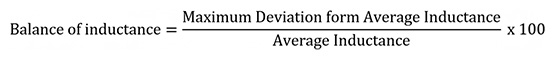
Inductance Testing: Inductance in motor circuits is routinely in the millihenry range. A motor test instrument is preferred but-an inductance bridge (LCR) may be used. Best test results are possible when the motor was run at load prior to testing. Motor circuits with surge/lightning arrestor or power factor correction should be tested initially with these components disconnected from the circuit, then trended with the normal circuit configuration. Any noted changes through trending for three-phase motor circuits the following formula can be used to determine the inductance unbalance:
Single-phase circuits are trended from baseline and/or compared with like motors. The most common connection point is the load side of the contactor.
Prior to testing, follow safety precautions to verify a zero-energy state. Voltage phase to phase should be < .5V and <5V to ground.
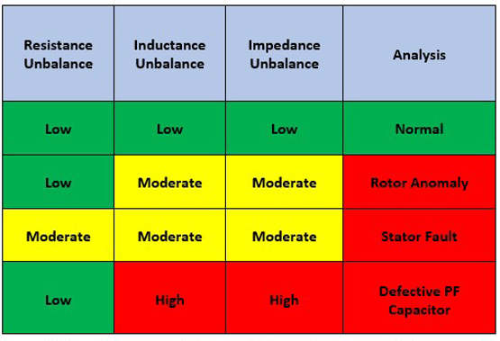
Troubleshooting Inductance Imbalance: Variance in inductance is normal due to positioning of the rotor. Through trending or by performing a baseline Rotor Influence Check (RIC), the normal variance may be established. Degradation of inductance values along with resistance, in correlating phases, indicates a stator fault. Variance in inductance with normal resistance readings indicates a rotor anomaly. High inductance unbalance with normal resistance balance indicates defective power factor capacitors.
Repairs for Inductance Unbalance: If a stator fault is indicated, a rewind or replacement would most likely be necessary. If a rotor fault is indicated, it may be the result of rotor bar or rotor core faults, or eccentricity. A RIC Test can be performed to resolve (some cases) the problem to the rotor or eccentricity. If the motor can be run at load, data can be correlated with MCSA, In-Rush, or vibration data. If the motor cannot be run at load, check the alignment and magnetic centering of the rotor.
If the rotor is suspect, but no correlation is conclusive, a core loss test can be performed on the rotor at a motor repair facility. The use of Flux paper and/or Infrared can be useful in localizing rotor defects.
Balance of Inductance Parameters: (Recommended)
Low Voltage Random Wound Motors:
>7% CAUTION
>12% ALARM
Medium High Voltage Motors:
>5% CAUTION
>7% ALARM
Applicable References for Inductance Measurement:


