A complete building inspection usually consists of two parts in which the conduction inspection needs to be completed before the air leakage inspection. In this tip discussion, we will cover the conduction inspection and the influence of air leakage during the inspection. During the conduction part of the inspection, the thermographer looks for anomalies or variations in the thermal pattern of walls and ceilings. These changes and differences can indicate missing, damaged, or incorrectly installed insulation. To successfully detect conduction losses or gains in a building it is absolutely necessary to have a sufficient ΔT between the inside surface and the outside surface of the walls. ASTM Standard C1060 recommends a stable ΔT of at least 18°F (10°C) between the inside surface and the outside surface of a wall to perform a conduction inspection on a building with IR.
Let’s assume we have the right conditions and sufficient ΔT to perform a conduction inspection on a building with IR. The thermographer must pay attention to any variations in the thermal pattern over the walls or ceiling as these may indicate areas with differences in the rate of conduction. This type of IR inspection can be complex, patterns and anomalies can be amorphous and indistinct. Therefore, we must pay attention to many important variables that can affect what we see with our cameras. For example, the type of insulation installed, placement of structural members and design elements, and the direction of heat flow as well as convective effects of the wind and solar loading on the outer surfaces, can affect walls and ceiling inspections with IR.
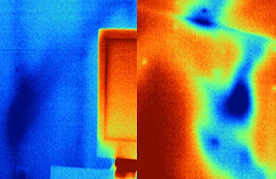
If we pay attention to the image above, we can see the structural elements of the ceiling in dark blue. We should also notice that in the ceiling tiles (the spaces between the structural support members of a commercial, insulated suspended ceiling), different areas appear in various shades of blue to yellow and orange colors. This type of thermal pattern can indicate that the conduction rates are not the same throughout the suspended tiles. We cannot determine the root cause of the differences until we perform further investigation.
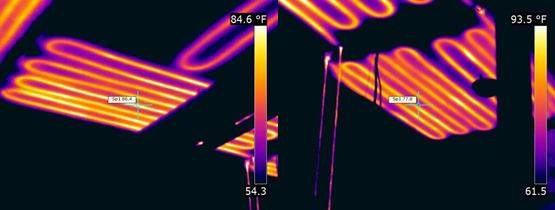
Below we can see two thermal images of walls with some irregular thermal patterns. These patterns could mean a variation in the insulation in the wall cavities, the presence of another system installed in the wall (plumbing, wiring, etc.), or it could even be moisture intrusion in the wall. Again, we won’t determine the root cause without further investigation. Look for systems installed in walls, floors, and ceilings such as radiant heat. In the images below, the radiant heat system is not in the floor, where most thermographers expect it to be, but in the ceiling.
To reiterate: conducting inspections with IR can be complex making it crucial to understand all the factors involved including the type of insulation, location of structural members, and location of any other systems. In the case that moisture intrusion is the likely culprit for observed anomalies this must be confirmed with a moisture meter.
To perform a successful conduction inspection on a building it is very important to have the right conditions and to follow the relevant standards for building inspections to avoid misinterpretation of abnormal thermal patterns. Understand that building construction, insulation type, and other systems in the building, along with environmental conditions, can affect what we see through our cameras. Having the proper training will go a long way toward gaining the knowledge necessary for performing this type of inspection and how to interpret any anomalies. Always take all factors into account when conducting a building inspection and remember to Think Thermally®!