Capacitance to ground measurement is fundamentally an early warning system that provides an indication that your motor’s insulation is on a path to degradation and failure. Taken during a standard EMT De-Energized Test, the Capacitance to Ground reading was originally intended as a trending tool to indicate dirt and moisture build-up on motor windings.
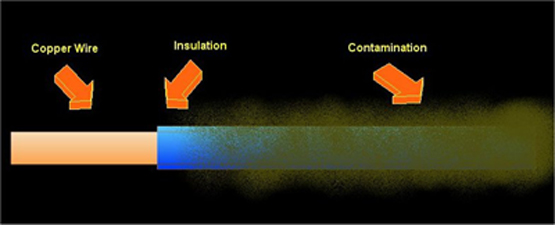
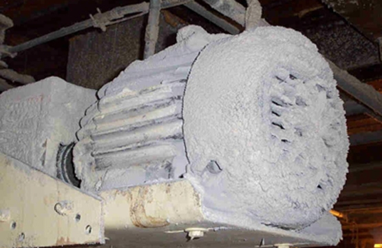
The capacitor is formed by the motor’s current-carrying conductors (usually copper) as one of the plates of the capacitor, and the motor core as the other plate. The insulation around the conductors acts as the dielectric for this capacitor. Adding contamination to the surface of the insulation changes the dielectric which increases the capacitance to ground value. The increase of contamination, essentially blanketing the insulation, will increase the winding temperature. The increase in winding temperature can cause the insulation to become embrittled. Embrittled insulation can crack and allow moisture or other contaminants into the windings, resulting in lower ground resistance.
Capacitance to Ground is also affected by the following:
- The temperature of the insulation
- Humidity
- Length of the cable
- The grounding system configuration
To ensure proper trending, somewhere in the notes section of the software, record the humidity and temperature. Testing at the same location is also extremely important as the cable length and other variables can also change capacitance to ground readings.
If you are testing an installed motor, a capacitance to ground reading <1000pF indicates that the motor under test is not properly grounded or may be affected by the system grounding configuration. Note if you obtain this reading make sure your test leads are connected properly.
Capacitance to Ground testing, when properly used and correlated with other insulation tests, can be extremely valuable in maintaining the longevity of your electric motors.