
Electric motors have been used in industry for nearly 150 years. The Gramme Machine, the first electric motor, was discovered quite by accident in 1873. Nickola Tesla invented the first practical AC electric motor in 1888 and they have been applied across all industry sectors ever since. According to the US Department of Energy, electric motors account for 60% of all industrial power consumption, and the typical electric motor will consume 5-12 times their purchase price in energy within their first year of service. Add to those facts the consideration that electric motors themselves are not inexpensive and replacing them is often a monumental maintenance task. As such, it makes sense to ensure that they operate in as healthy a state as possible.
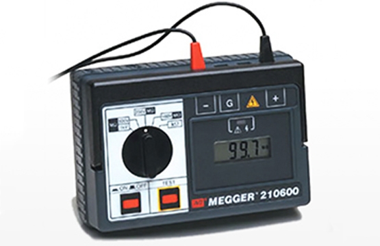
For many years, electricians have relied upon resistance to ground testing to determine motor health. Meg-ohmmeter testing is an electrical test of insulation performance in an electrical apparatus. A mega-ohm meter is applied to each phase connection for the motor leads and ground, and a voltage is applied. The meter measures the amount of voltage that drops across the connection point between the motor leads and ground and calculates an insulation value that is displayed to the user. The expectation usually is that a higher resistance number is better, which is often the case. In a best-case scenario, the figures are trended over the service life of the motor and used as an indication of impending failure.
This practice is still widely used in many settings and often is a Preventive Maintenance (PM) action performed at a scheduled interval. Often though, motor failures cannot be predicted with this testing protocol due to the limitations of the method itself. Meg-ohmmeter testing measures the resistance between the phase windings of the motor under test and ground. If there is an insulation breakdown, the resistance is negatively impacted and there is a departure between phases or between one measurement and a previous one and a determination of motor health is made. The problem with testing with a meg-ohmmeter is in its limitation. All it measures is resistance to ground. Most electrical motor failures begin with insulation breakdown, however, not between phases and ground, but instead between sets of windings within a phase or between windings of differing phases. Resistance to ground testing alone is not able to identify this type of failure.
Resistance measurements of windings are often added as another testing method to complement Meg-ohmmeter testing, with the expectation being that changes in resistance would be an indicator of imminent failure just like resistance to ground. Again, this testing method cannot always find a winding-to-winding short. While it is true that resistance measurements will be impacted in a turn-to-turn short, the impact is often minimal on resistance alone. There is however a greater impact on the impedance across the windings. Most multimeters test resistance, not impedance, and unfortunately, many electricians are under the impression that resistance and impedance are the same things.
Electrical resistance is an opposition to electrical current, while electrical impedance is an opposition to a change in electrical current. Resistance and impedance are somewhat similar, but not the same and cannot be measured in the same manner. Often in the case of turn-to-turn shorts in motor windings, there will be a change in impedance that cannot be detected with a simple multimeter measurement.
In order to get a more accurate measure of the electrical health of an electric motor, more than resistance to ground testing must be undertaken. Polarization Index (PI) testing is similar to testing with a Meg-ohmmeter in that it measures the resistance from windings to ground to determine the health of the winding insulation. The difference is that a PI test measures resistance at one minute, and then again at 10 minutes, and a ratio is measured. Healthy winding insulation will exhibit an increase in resistance over the measurement period, indicating that the insulation has been polarized. Brittle insulation won’t have the same change will not show the same increase in resistance.
Surge comparison testing has been in use for the last 40 years or so, but only recently in wide use. Surge testing is premised on there being no difference in the three phases of windings within a motor if there are no defects present. With coil-to-coil and turn-to-turn shorts, the response to the applied voltage surge (hence the name surge comparison testing) will be different than in windings with no defects. This type of test is the only method presently available that will detect these early defects that in time become larger issues impacting motor health.
Resistance to ground testing is good and has its place in a motor testing regimen, but it need not stand alone. Along with the other test methods discussed here, motor health can be assessed from a much broader perspective, leading you to greater overall motor asset health.