Training Schedule
Training for Infrared and EMT professionals world-wide.


When creating an infrared inspection report it is important to include a high-quality visual reference of the anomaly along with the thermal image in the report. This visual image, along with written directions, will help the individuals responsible for the repair quickly find the equipment or component where the thermal abnormality exists.
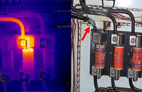
The visual image also plays another important role, helping the thermographer better understand the thermal abnormality found during the inspection. The visual image should help the thermographer to provide diagnostics and suggestions concerning the needed repairs or possible causes for the thermal abnormality. For example, below you can find both the thermal image and the visual image of an inspection made on some electrical fuses. The thermal image on the left shows a thermal abnormality in one of the electrical connections in the fuse clip or block of the center phase. If we take a close look at the visual picture reference (above), we will be able to see that there is also a problem with the electrical insulation of one of the cables on the left electrical phase.
Providing a visual reference image in your report provides the recipient with more information about the thermal abnormality, leading to better documentation of the problem and what was done to rectify it. A good suggestion to pass on to the client is to include a before-and-after set of images in their documentation, illustrating that the problem has been repaired.
When a thermographer is performing an IR electrical inspection it is important to try to find any thermal abnormality on the infrared images, but to also look for visual indications, such as discoloration, that a device could be running above the normal temperature. Keeping in mind that the heating may should a visual change in the material that would cause the emissivity to increase making an otherwise difficult to find fault easier to “see “in the thermal. Other visual indications can include, but are not limited to:
Remember to use your eyes as well as your IR camera. Always keep an eye out for code violations, corrosion, scorch marks, discoloration, missing insulation, improper size or type of components, and any other visual indications that there could be a problem.
Many of the thermal cameras on the market today include an integrated visual camera. It’s important to note, however, that you should be sure the onboard visual camera takes images with a high enough quality to provide a useful visual reference of the thermal image. Some thermal cameras include a flash or light to use with the visual camera but if not, it will be necessary to have an external flashlight. If the onboard visual camera quality isn’t great, it might be necessary to take a visual picture with a separate digital camera with better or higher resolution. For example, when a telephoto lens or wide angle is used on an infrared camera, the visual image may not match up. A separate digital camera can help with this. If your thermal camera doesn’t have an integrated visual camera an additional digital camera will definitely be necessary.
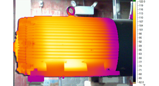
You may also see infrared cameras that have the ability to make a “blended” infrared and visual picture, or have “Picture in Picture” capability, showing both the thermal and the visual image. Keep in mind, the blending technology used today can provide misleading infrared results. The resolution can appear to be higher than it actually is, as the details seen in the image are visible, not thermal. There are also cameras that have a feature which allows you to set an alarm to only show in thermal vision the parts of the image that are between certain designated temperatures within the thermal span that is being used, and the rest of the image will be shown as a visual picture (see example below).
The benefits of including a visual reference image in your IR inspection reports should be more than apparent now. It will help make the job easier for the individual(s) performing the repair, it will help you to better understand and diagnose the problem, and it is invaluable in helping the client document the problem and the resolution. As the saying goes, “A picture is worth a thousand words,” and in the world of thermography, it’s probably worth even more than that.


