Training Schedule
Training for Infrared and EMT professionals world-wide.

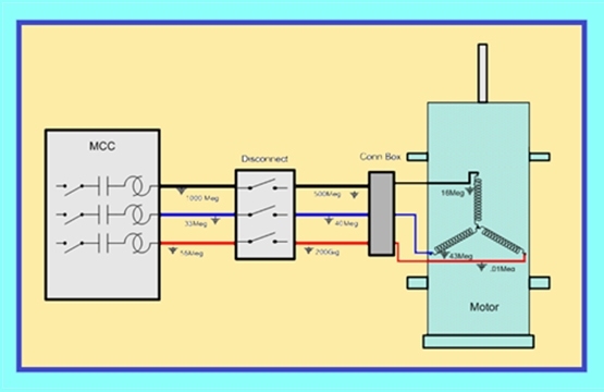
A -“T” Leads, B-Local Disconnect, C-Motor Connection Box (above)
Electric motor test instruments are designed specifically for motor testing. However, when in the hands of a properly trained and savvy technician or engineer, they can be utilized for considerably more testing and diagnostics. In this testing tip, we will discuss how to utilize motor test instruments to diagnose problems with the cabling and distribution circuit of the motor.
When conducting de-energized electric motor testing, connections are usually made at the motor “T” lead terminals in the motor starter. This provides for the evaluation of the motor and associated cabling. When presented with a ground anomaly or a resistance unbalance the first step is to localize the problem to the motor or cabling. If a disconnect is present in the circuit, it can provide an immediate point of isolation. Open the disconnect and retest from the load side of the open disconnect. If the problem is no longer present the problem is in the line side of the disconnect or within the interconnecting cabling. If the problem is still present, the problem is somewhere between disconnect and motor or in the motor. The next step would be opening the supply cables at the motor connection box. Conduct testing on the isolated motor. If the anomaly is present, the problem is in the motor. If the problem is not present it is in the cabling from the load side of the open disconnect. If the problem is a resistance imbalance it is most likely the disconnect terminals. Short all 3 cables together at the motor and measure the phase-to-phase resistance from the disconnect terminals. This will isolate the phase with the connection problem. If you measure 1-2, 1-3, and 2-3 the phase with the highest resistance measurements is the problem. For example, if 1-2 and 1-3 had higher resistance than 2-3, phase 1 is common to the higher resistance readings, the connection anomaly is in phase 1.
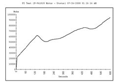
When a ground fault is present you will isolate in a similar manner except if it is isolated to the cabling, you will leave the cables disconnected at the motor with an open disconnect or open starter if there is no disconnect in the circuit. Each cable will require a resistance to ground test performed to determine the phase with the ground fault. Below is a Case Study on a 4160V 250HP Acceptance Test:
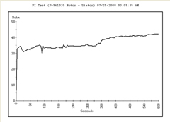
The motor was part of a new plant installation. Prior to the testing on the left, the motor was tested separately and the individual disconnected cables were tested with a High Potential (Hi-Pot) Tester to 20,000V. Everything appeared to be fine. Once all connections were made, a few weeks later the entire circuit was tested with a motor test instrument. All tests were normal except for the timed resistance test or Polarization Index. The minimum ground resistance acceptance value, required by the facility was 100 Megohms.
The PI was low and the maximum resistance to ground was well below the required 100 Megohms. The phase cables were disconnected at the motor, and they were tested individually. The results are below:
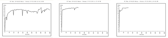
All 3 cables displayed approximately 13 Megohms. It is highly unusual to have exact readings on phase cables. Something had to be common to all three. The cables that were disconnected at the motor had insulated boots over the conductors. The other end of the cables were terminated in the starter with the main contactor de-energized, essentially open at both ends.
The only common point was the insulator terminal in the starter.
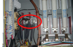
The phase 3 terminal was removed, and the cable retested. The results on the left show a drastic change in ground resistance, a value you would expect on new installations, 100,000 Megohms. The insulator terminal was defective.
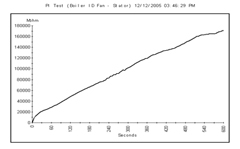
In another Case Study, a motor with defective bearings was being replaced with a spare. We were asked to check the motor before it was connected to the power circuit. The motor was a 4160V 1500HP boiler ID Fan. The motor was tested with excellent results. The supply cabling was tested and an extremely high Polarization Index of > 9.0 was obtained.
With motors, depending on the type of insulation applied, a PI greater than 4.0 would indicate possible embrittlement. We made a judgement, given the location of the motor supply cables, running in and around the hot boiler the cabling could be embrittled and that it would be prudent to recommend cable replacement. The customer determined that cable replacement was unnecessary and cost prohibitive. Six months later the cable failed.
Motors are just a part of a motor circuit that is being supplied by the facilities electrical distribution system. Anomalies that present a failure mechanism to the motor can be at any point in that system. It is because of this that we have to monitor all aspects of the motor, power circuit, and distribution systems. In this Tip, we have only talked about isolating a problem in the supply cabling. Energized motor testing and power quality monitoring are also a vital part of monitoring your motors health. Electric Motor Testing is a powerful tool for your plant’s reliability program. If you’d like to learn more, consider attending our Electric Motor Testing—Energized & De-Energized Certification Course.


