Training Schedule
Training for Infrared and EMT professionals world-wide.


In our Level I Thermographic Applications course we mention that there are many types of mechanical systems where thermography is a correlating or validating technology. We also talk about several types of systems in which thermography is a great fit and can reveal failure modes as well or better than other technologies. Piston driven air compressors fit into the latter category.
Due to the buildings’ application of thermography, in particular air leakage inspections, some maintenance people will assume thermography can be used to detect leaks in compressed air systems. While this is theoretically possible, it’s not your best approach. Airborne ultrasonic detection is the tool of choice here. When thinking about the types of compressors you might have seen in operation, what comes to mind might be the large, enclosed industrial air compressors. These compressors are tougher to inspect than the smaller units with the operating components readily accessible.
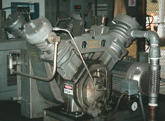
Almost every industrial facility has the need for compressed air for numerous reasons. Often, you’ll find various sizes and types of compressors, including piston driven types, as you see to the right. This type of configuration comes in various sizes, including portable compressors. This is one of the oldest and most widely used types of industrial compressors. It uses displacement to increase the pressure of a closed volume of air.
All air compressors are driven by a motor, typically an electrical one, although there are very large-scale compressors driven by natural gas motors. Piston driven air compressors are actually comprised of several different types of mechanical components. A seasoned thermographer might be familiar with inspecting the electric motor; bearings on the motor, the case of the motor itself, and the motor connection box. All of these parts are opportunities to discover defects. The belts driving the pistons can be inspected for misalignment, proper belt tension, belt slipping, or sheave wear. Any mechanical couplings in the system can be inspected for alignment or wear heating as well.
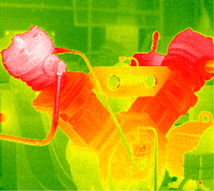
One part of the air compressor system that is specific to them is the heads. As in any other type of piston driven system (think about your car engine), the heads are where the valves are located. Many end users of compressed air systems report valve failure as a leading cause of unplanned downtime. The temperature of the cylinder head is a leading indicator of the failure of the valves. Generally speaking, it doesn’t matter if it’s the suction valve or the outlet valve that is beginning to fail. Either will cause a disparity in valve cover temperature. In a single-stage system, the head temperatures should be close to the same. Two-stage compressors, however, are different. The second stage head will almost always run warmer, as in the example to the right. Because of this, it’s important to understand the type of compressor before making a determination about the thermal condition. Another great inspection option is the air cleaners. A dirty or clogged air cleaner operates at much high temperatures than a clean filter. With a basic level of understanding, you’ll find that air compressor failure modes may be effectively discovered directly from learning to Think Thermally®.


