Training Schedule
Training for Infrared and EMT professionals world-wide.

Monitoring motor circuit resistance is of critical importance. A slight increase in resistance can have a significant effect on the balance of resistance on 3-phase motor circuits.
An increase in resistance will show the effects with an increase in heat. It is a function of resistance and the current flowing through the connection and can be quantified in watts. Mathematically expressed as I2R or the current squared times the resistance, yields a value in watts. Infrared works well in identifying problems where visible access is possible. Motor circuit resistance measurements evaluate the entire circuit. Resistance, quite simply, is opposition to current flow.
Physical properties that affect resistance:
Unbalanced resistance can cause localized heating at problem connections, (I2R). Connection problems can develop over a prolonged period or develop rapidly. The primary effect on a motor is unbalanced current.
Some external influences may affect resistance. Fans and pumps may have the rotor continue to turn when the motor is off. Energized heater circuits can also affect resistance. Both can induce voltage that may corrupt data.
Common causes of connection problems:
Resistance Testing: Resistance in motor circuits routinely is in the milliohm range. On large medium and high voltage motors, it may be measured in the microohm range. A motor test instrument is preferred but a digital low-resistance ohmmeter (DLRO) may be used.
For three-phase motor circuits the following formula can be used to determine the resistance balance:
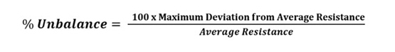
Single-phase circuits are trended from baseline and/or compared with like motors with comparable cable run lengths.
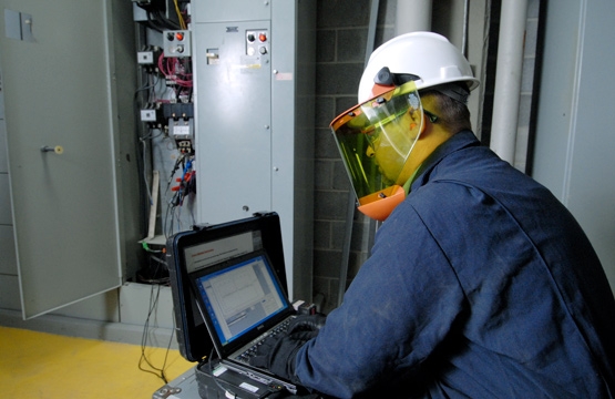
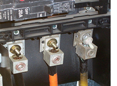
Prior to testing, follow safety precautions to verify a zero-energy state. Voltage phase to phase should be < .5V and <5V to ground. Test as much of the circuit as possible. The most common connection point is the load side of the contactor. If possible, test the overloads.
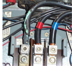
Troubleshooting Resistance Unbalance: Many connection problems may be identified through visual inspection. Discoloration of conductors, terminations, burnt or embrittled insulation, and frayed conductor strands, are all signs of a possible connection fault. Infrared may also effectively be employed when the circuit is energized and at >40% load.
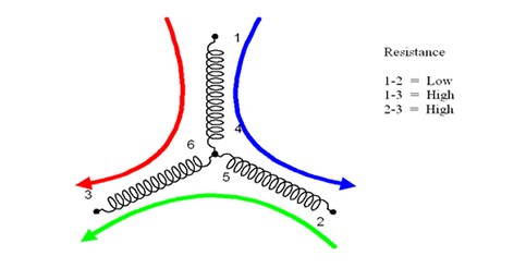
If a visual or IR inspection does not localize the problem, look for the phase measurements that exhibit the highest resistance. The phase common to the higher resistances is the location of the resistance anomaly, relative to the test lead connection points.
Next split the circuit at easily accessible points, i.e., local disconnect or junction box. Measure again; if the unbalance is gone the problem is upstream from your measurement point. If the problem is isolated to the motor, before disassembly or removal, cut back the insulation around the lugs at the motor leads and re-measure. If the unbalance is gone the problem is most likely poorly crimped connections on the motor leads.
Repairing Connection Faults: In over 50% of the corrective maintenance efforts, repairs are not successful the first time. The primary reason for this annealing. If conductors and connections are exposed to temperatures of approximately 200o F, for around 30 days annealing has possibly occurred. The physical and conductive properties of the materials have changed and therefore need to be replaced. This is of particular importance where spring tension is a part of the connection, such as fuse clips, contactors, and circuit breakers.
Balance of Resistance Recommended Parameters:
When testing the entire motor circuit:
>3% CAUTION
>5% ALARM
When testing at the motor:
>1% ALARM
Applicable References for Resistance Measurement:
For more information on electric motor testing, consider attending one of Snell Group’s innovative motor testing training courses.


