Training Schedule
Training for Infrared and EMT professionals world-wide.

Infrared inspections of mechanical systems can be challenging. Working knowledge of the machinery or component is absolutely necessary to successfully interpret these images. This is especially true when inspecting hydraulic systems which are some of the most widely used pieces of equipment in plant operations.
Now, when I am talking about hydraulics, I am not just describing a system that causes an actuator to move up and down or a fluid-powered motor to rotate. What I mean is any process that uses fluids to do work or accomplish some sort of task. Most all fluid moving systems have similar components.
Reservoirs
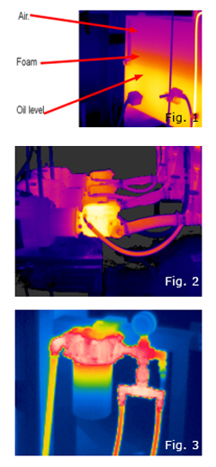
Use infrared to detect fluid levels. Also, with the right span setting, contaminates such as solids, water or foam can be detected thermally. Sediment, foam, water, or even dissimilar fluids have different thermal capacitances that in turn affect the surface temperature of the reservoir, creating thermal differences which we can detect on the wall of the tank (figure 1).
Pumps
These can be inspected by first looking for abnormal temperatures by comparing similar pumps. Abnormal pump temperatures can be a result of over or under pressure, abnormal flow, cavitation, internal wear, and others. It is best to use a trending methodology when inspecting pumps where you monitor images of that pump over time and look for any changes in the pattern (figure 2).
Filters
Most filters are equipped with a bypass valve. The theory for having a bypass valve placed in a filter is that it is better to have dirty oil moving in the system than no oil at all. The filter body should appear to be around the same temperature as the rest of the system. If a filter appears cooler it may be the result of a dirty filter, air lock, or a stuck bypass valve (figure 3).
Accumulators
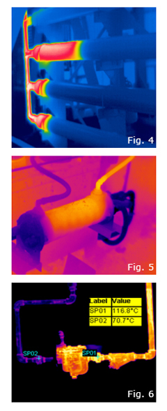
An accumulator, used to store fluid energy, can make up the difference between what flow a pump can produce and the flow needed to do the work. By using an accumulator, a smaller pump can be installed, saving in both the cost of the pump and the energy used to drive it. There are a few different kinds of accumulator designs, such as piston, bladder, and diaphragm. All of which use a gas charge (normally nitrogen) to push the oil out of the accumulator. No matter what type of accumulator is being inspected, the same thermal pattern should be expected if the system is relying on the accumulator for proper operation. A thermal difference should be seen between where the hydraulic oil is walled off, or separated, from the gas fill. The oil side should be warmer than the gas side. If the accumulator appears to be close to the same temperature throughout its length, it is most likely not functioning properly. Only one of the four accumulators in the above image is working properly (figure 4).
Heat Exchangers
Properly operating heat exchangers should exhibit a temperature drop across the inlets to outlets of the fluid being cooled. The cooling medium should show a temperature rise from inlet to outlet, indicating it is carrying the heat away from the system. This rise or drop, depending on the section of heat exchanger you are viewing, will normally be no more than 10 to 20 degrees. Check with the system designer to verify proper temperatures (figure 5).
Valves/Steam Traps
It is possible to inspect values with infrared but an alternative technology such as ultrasonics might be a better tool. When inspecting valves for proper operation with IR you must know the flow pattern. Understanding this will allow the inspector to look for thermal patterns that verify where the warm fluid is passing or not passing. In some cases, you may find that the system indicates it is running, but no work is being accomplished. Just because the motor is running, and the pump is operating it doesn’t necessarily mean that the system is operating. Knowing what to look for and where to look is critical to a fluid system inspection with thermal imaging (figure 6).


