Training Schedule
Training for Infrared and EMT professionals world-wide.

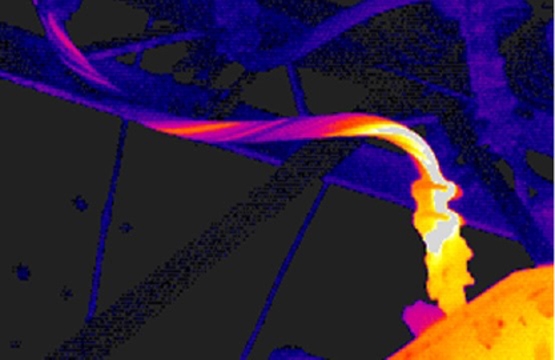
The image above is from a tight radius on a large conductor with a mechanical crimp.
All reliability maintenance equipment is multi-faceted and can be used to identify most developing anomalies. Each technology has its own unique capabilities but can overlap with other technologies. Electric motor testing and Infrared Thermography present a significant capability for identifying connection anomalies, aka “high resistance connections.” Utilizing both infrared and motor testing, with regular periodicity can all but eliminate circuit connection problems. Infrared is highly effective for finding connection faults in areas where visual access is possible. Electric motor testing identifies resistance or current unbalances and then they must be systematically isolated. Let’s look at connection problems:
First, we must discuss resistance. Resistance, opposition to current flow in a circuit. Connection anomalies pose resistance problems in our motor circuits and if they are not identified and corrected, they can have deleterious effects. Normal things that affect circuit resistance are:
The above are physical properties for which we have little or no control. Unfortunately, most resistance anomalies in our motor circuits are self-imposed. This includes but not limited to:
Resistance anomalies create heat, which increases resistance, which creates more heat, which creates more resistance. The cycle continues until you either find the problem or it finds you. It can thermally degrade to the point of catastrophic failure.
Combining Ohm’s Law and Watt’s Law, we transpose equations to resolve P = I2R or Power is equal to the current flowing in the circuit squared, times the resistance its flowing through, which can be quantified in Watts.
For example: assuming 1 ohm of resistance:
5 amps = 52 x 1 ohm = 25 Watts
The problem is exacerbated by current increasing, let’s double the current:
10 amps = 102 x 1 ohm = 100 Watts
Doubling current didn’t double the wattage loss, it quadrupled it!
With most motor circuits we are dealing with extremely low resistance values in the micro to milli-ohm range. Given that, it doesn’t take much to cause a significant resistance problem.
Almost all resistance problems are self-imposed, let’s look at some of the poor practices that create such problems. Achieving proper torque is essential. How many of you use torque wrenches? Every fastener has a torque specification. Why not use a torque wrench. Less that 5% of industrial facilities utilize torque wrenches, including a number of the more regulated industries. Improper crimps, multiple conductors in one lug, improper wires size vs. terminal lug, broken and cut conductor strands are some of the
self-induced termination faults. These can be alleviated by having set procedures for making up crimps and connections, with procedural adherence. Local disconnects are notorious sources of high resistance. One of the most common problems is arcing and subsequent pitting, which reduces contact surface area, from operation while under load. Disconnects are for equipment isolation during maintenance, not an on or off switch.
With proper maintenance practices and procedures, connection anomalies can all but be eliminated. For more information on causes of resistance problems and infrared and electric motor testing. Contact the Snell Group and schedule one of our comprehensive training courses. Don’t forget to ask about our new De-Energized Electric Motor Data Analysis Wall Chart. A 36” x 48” laminated chart that is a wealth of information. Also, keep a lookout for our Energized Electric Motor Data Analysis Wall Chart. This should be making its debut early next year.


