Training Schedule
Training for Infrared and EMT professionals world-wide.

The core material used in motor stators and rotors is critical to efficient operation and longevity. Motor stators and rotor cores are comprised of thin sheets of steel that are stacked together and insulated from each other. The composition of this steel is highly specialized to minimize the heating effects of hysteresis and eddy currents. Only a handful of steel mills, worldwide manufacture this specialized product.
ASTM A664 provides standards for the grading of this steel by use of a process known as the Epstein Test. This test measures the overall losses of the steel measured in watts per pound. The losses range from around 1.75 to 10 watts per pound. The composition of this “electrical steel” is rarely provided in the specifications of procured motors. You can be reasonably certain that the cheaper motors utilize cheaper steel that will exhibit higher losses, which means the motors will run hotter.
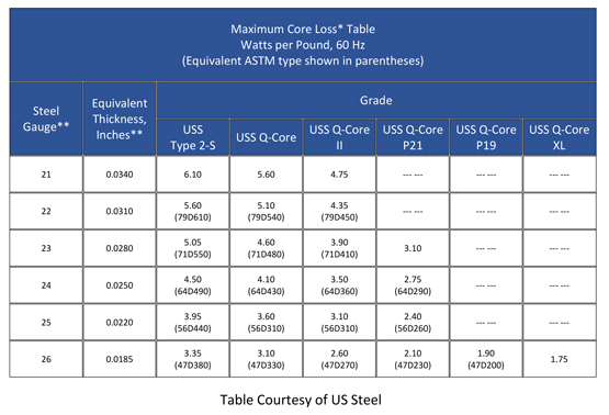
The table below provides the specifications of some of US Steel’s specialized “electrical steel.” The number in parenthesis is the ASTM designator. The first two digits represent the nominal thickness in millimeters. The code letter “D” is the magnetic material category. The last three digits represent the maximum core loss in watts per pound. As you may note there is quite a variance in rated core loss, depending upon the grade of steel utilized.
So why is this important? When a motor is sent in for rewind, part of the process involves a procedure known as “burnout. The stator is heated to a maximum of 700oF, 370oC. This process removes all of the old insulation and makes “stripping,” (removal of the old windings,) easier. Burnout is the number one cause of core damage! The burnout process is critical and must include the following:
Motor stators are core tested by most motor repair facilities. It can be accomplished by use of a commercial core loss tester or by use of a Loop Test. These all depend upon the dimensions of the stator and are described in detail in the following publications:
Unless specified in your rewind procedures, provided to the motor repair facility, core loss testing is usually performed prior to installation of the new windings. It is prudent to require a pre-burnout and post burnout core loss test. This insures that the stator is initially suitable for rewind and that no damage has occurred during the burnout process.
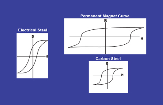
The stator core is designed to enhance the magnetic field in the stator, minimize hysteresis and minimize eddy currents.
The graphs at the top of the page, or magnetic hysteresis curves, display and compare the magnetic properties of electrical steel, carbon steel and a permanent magnet. The magnetic properties for each are plotted on a XY plot that shows the flux density, B against the field intensity, H. These are known as B/H curves. Core damage affects the magnetic properties as well as yielding abnormal eddy currents.
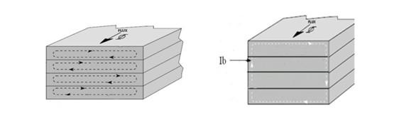
The above images show normal eddy currents that are contained within each individual laminate (on the left) and interlaminar eddy currents caused by core damage (on the right).
It is important that you identify what type of core material is used in your motors so that a more realistic core loss specification is utilized for overall assessment of your stators when sent in for rewind. Motors should be operated within their temperature range to prevent possible insulation and core damage. Last and most importantly, core loss testing should be required before and after burnout and in your motor rewind specifications.


