Training Schedule
Training for Infrared and EMT professionals world-wide.


The use of impedance values can provide a rapid and conclusive means of localizing the source of anomalous data to the rotor, stator, or motor circuit. All of the major motor tester manufacturers provide various data formats to achieve analysis.
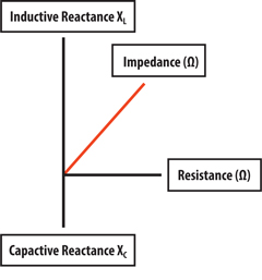
Let’s look at the basics. Impedance is the vector sum of resistance, inductance, and capacitance. Inductance and capacitance are 180 degrees apart in their phase relationship and 90 degrees displaced from resistance. The vector sum of these values is “impedance.”
Inductance and Capacitance are physical properties that do not change regardless of frequency. They will only change with degradation, opens, shorts, etc. To determine impedance, we measure the reactance of the Inductance (XL) and reactance of the Capacitance (XC). Their respective values are expressed in Ohms. The drawing below shows the vector relationship:
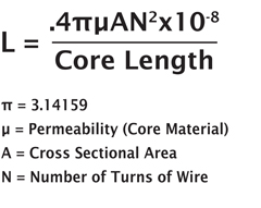
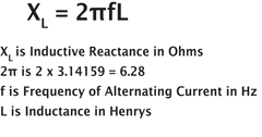
When measuring a motor circuit, there is virtually no phase-to-phase capacitance, so we are primarily evaluating the relationship between phases using inductance and resistance. Inductance is affected by everything within the motor. Observe the formulas, below, for Inductance and Inductive Reactance (XL):
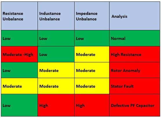
The table below provides an excellent resource for determining motor faults and location for many of the static motor test instruments and their acquired data sets.
Note: If you exhibit an inductance unbalance and balanced resistance with the rotor removed; look for incorrect wiring, such as a reversed coil.
By understanding the relationships of the component values within the formula for inductance, one can see that any damage to the stator core or rotor core, rotor position within the bore of the stator, and in particular any effect to the number of turns, as it is a square function, will affect inductance.
Any effect on the inductance, caused by an anomaly within the motor, will influence the inductive reactance and will affect the Ohm value of the reactance. The change in reactance will have an inverse effect on current. If XL increases, current decreases. If XL decreases.
Motor windings and circuit cabling is measured for resistance using a DC voltage. The amount of voltage drop reflects the DC resistance of the circuit. Resistance is affected by the length of the wire, temperature of the wire, and the diameter of the wire.
Through observation of inductance, impedance, and resistance it is possible to easily identify faults and isolate the fault to the motor windings, rotor, or circuit connections. Rotor design, position, and condition can have a significant effect on inductance and impedance. It will not have any effect on circuit resistance. A motor that exhibits an inductance and or impedance unbalance, but has balanced resistance is usually indicative of a rotor-induced fault. It should be noted that many rotor designs exhibit a moderate inductance and impedance unbalance.
For this reason, acceptance testing upon receipt and baseline testing upon installation is essential. Changes in trended inductance and impedance are usually related to rotor position. If the unbalance percent increases without a corresponding increase in resistance unbalance, check for recent maintenance actions that may affect rotor position. This may include belt replacement, alignment, coupling maintenance, etc. If no maintenance action has been performed, it is necessary to determine the reason for the change. This may be accomplished by the performance of a Rotor Influence Check (RIC) or online current signature analysis.
When inductance and/or impedance unbalance are accompanied by a corresponding resistance unbalance, the cause is stator related. If lower resistance inductance and impedance are related to one phase, the cause is most likely shorted turns within that phase. If lower resistance, inductance and/or impedance are correlated to a phase to phase measurement, the source is most likely a phase-to-phase short. If additional testing such as surge, hi-pot, or current frequency response is not available, the unit should be replaced.
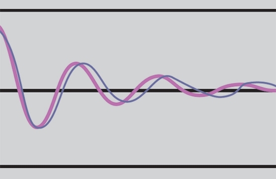
Surge testing evaluates winding balance, by discharging a capacitor through the windings creating a “tank circuit.” The waveform (example, Figure 1) for this discharge should be the same for each phase measurement and continue as the voltage is raised.
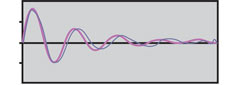
Figure 1: Two waveforms to be compared
Motor circuits that exhibit an increase in resistance related to one phase, without any effect on inductance, are indicative of a developing high resistance connection.
In summary, by using Resistance and Impedance it is relatively easy to localize the cause of the indicated anomaly. This topic and the theory necessary to properly test and maintain motors are covered in detail in The EMT Level I Offline Course currently offered by The Snell Group.


