In our continuing series about motor testing and the various tests available, in this segment we are going to discuss motor circuit resistance measurement. Monitoring motor circuit resistance is of critical importance. A slight increase in resistance can have a significant effect on the balance of resistance on 3-phase motor circuits.
An increase in resistance will show the affects by the creation of heat. It is a function of resistance and the current flowing through the connection and can be quantified in watts. Mathematically expressed I2R, or the current squared times the resistance yields a value in watts. Infrared works well in identifying problems where visible access is possible. Motor circuit resistance measurements evaluates the entire circuit. Resistance, quite simply, is opposition to current flow.
Physical properties that affect resistance:
- Length of the wire
- Temperature of the wire
- Wire material (Cu, Al)
- Cross sectional area
- Stranded vs. Solid
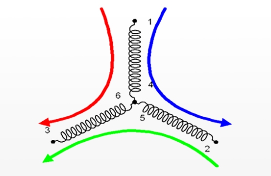
Unbalanced resistance can cause localized heating at problem connections, (I2R). Connection problems can develop over a prolonged period or develop rapidly. The primary effect on a motor is unbalanced current. Unbalanced resistance can result in negative sequence currents, causing an increase in operating temperature leading to thermal degradation of the insulation. Worst case, it may result in single phasing.
Some external influences may affect resistance. Fans and pumps may have the rotor continue to turn when the motor is off. Energized heater circuits can also affect resistance. Both can induce voltage that may corrupt data.
Common causes of connection problems:
- Loose / over tightened connections
- Improper wire / lug size
- Frayed conductor strands
- Poor Lug crimps
- Fuse clip tension
- Arced and pitted contact surfaces
- Multiple leads in a single lug
- Dissimilar metals at connections
- Factory splicing in cable
- Unequal component sizing (fuse, overload)
Resistance Testing: Resistance in motor circuits routinely is in the milliohm range. On large medium and high voltage motors it may be measured in the microohm range. A motor test instrument is preferred but a digital low resistance ohmmeter (DLRO) may be used. For three phase motor circuits the following formula can be used to determine the resistance balance:

Single phase circuits are trended from baseline and/or compared with like motors with comparable cable run lengths.
Prior to testing; follow safety precautions to verify a zero energy state. Voltage phase to phase should be < .5V and <5V to ground. Test as much of the circuit as possible. The most common connection point is the load side of the contactor. If possible test the overloads.
Troubleshooting Resistance Unbalance: Many connection problems may be identified through visual inspection. Discoloration of conductors, terminations, burnt or embrittled insulation and frayed conductor strands, are all signs of a possible connection fault. Infrared may also effectively be employed when the circuit is energized and at >40% load.
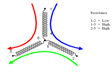
If a visual or IR inspection does not localize the problem, look for the phase measurements that exhibit the highest resistance. The phase common to the higher resistances is the location of the resistance anomaly.
Next split the circuit at easily accessible points, i.e. local disconnect or junction box. Measure again; if the unbalance is gone the problem is upstream from your measurement point. If the problem is isolated to the motor, before disassembly or removal, cut back the insulation around the lugs at the motor leads and re-measure. If the unbalance is gone the problem is most likely poorly crimped connections on the motor leads.
Repairing Connection Faults: In about 50% of the cases, repairs are not successful the first time. The primary reason for this is annealing or increased oxidation. If conductors and connections are exposed to temperatures of approximately 200o F, for around 30 days annealing has possibly occurred. The physical and conductive properties of the materials have changed and therefore need replaced. This is of particular importance where spring tension is a part of the connection, such as fuse clips, contactors and circuit breakers.
Balance of Resistance Recommended Parameters:
When testing the entire motor circuit:
>3% CAUTION
>5% ALARM
When testing at the motor:
>1% ALARM
Applicable References for Resistance Measurement:
- ANSI/EASA AR100, Recommended Practice for the Repair of Rotating Electrical Apparatus.
- IEEE Std 118TM, (withdrawn) IEEE Standard Test Code for Resistance Measurement.
- IEEE Std 389TM, IEEE Recommended Practice for Testing Electronics Transformers and Inductors.
- IEEE Std 1415, Guide to Induction Machinery Maintenance Testing and Failure Analysis
For more information on electric motor testing, consider attending one of Snell Group’s innovative motor testing training courses.