Motor tester manufacturers provide us with a number of different test capabilities that provide valuable information for assessing motor and motor circuit condition. One of these data sets is Impedance.
Impedance is the measure of the opposition that a circuit presents to the passage of a current when a voltage is applied. In quantitative terms, it is the complex ratio of the voltage to the current in an alternating current (AC) circuit. Impedance extends the concept of resistance to AC circuits, and possesses both magnitude and phase unlike resistance, which has only magnitude. The value of impedance and phase angle is determined by the resistance and reactance (inductive and capacitive) in a circuit. When a circuit is fed with direct current (DC), there is no distinction between impedance and resistance; the latter can be thought of as impedance with zero phase angle.
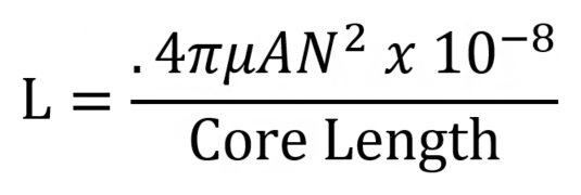
L = Inductance
π = 3.14
μ = Permeability (Core Material)
A = Cross-Sectional Area of the Core
N = Number of turns
Unbalanced impedance can indicate degradation of the motor core and windings as well as problems with the rotor, rotor core and rotor positioning in relation to its magnetic center. Inductance is a component of impedance which is affected by virtually everything within the motor, as can be determined by the above formula. Unbalanced impedance can cause current unbalance and excessive vibration, depending on the source of the unbalance.
Some external influences may affect impedance. Power factor correction capacitors and surge/lightning arrestor circuitry affect the reactance when measurements are taken.
Common causes of Stator related impedance unbalance:
- Shorted turns, coils, phases
- Laminated core damage
- Defective power factor capacitors
- Defective surge/arrestor circuitry
Common causes of Rotor related inductance unbalance:
- Rotor design
- Radially and/or axially out of magnetic center (eccentricity)
- Broken, cracked, high resistance, porous rotor bars
- Rotor core damage
Impedance Testing:
Impedance in motor circuits is measured in Ohms. A motor test instrument is preferred but-an inductance bridge (LCR) may be used. Best test results are possible when the motor was run at load prior to testing. Motor circuits with surge/lightning arrestor or power factor correction, should be tested initially with these components disconnected from the circuit, then trended with the normal circuit configuration.
Single phase circuits are trended from baseline and/or compared with like motors. The most common connection point is the load side of the contactor.
Prior to testing; follow safety precautions to verify a zero-energy state. Voltage phase to phase should be < .5V and <5V to ground.
When performing any type of diagnostic or periodic maintenance, it is important that we use every data set as part of our diagnosis or assessment. Impedance as a “stand alone” value can be difficult and misleading when trying to localize a motor or motor circuit fault. It must be correlated with other values such as inductance, resistance and phase angle, to provide accurate conclusive results.