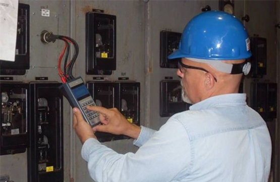
Energized electric motor testing requires access to voltage and current in order to provide the data necessary to fully evaluate the motor and motor circuit condition. With medium and high voltage motors it is a given that to accomplish this safely, connections must be made on secondary low voltage circuit, potential and current transformer outputs (CT’s and PT’s). With the ever-increasing electrical safety requirements limiting access to open electrical enclosures, low voltage equipment’s, < 1000V, are now being configured with secondary circuits. These circuits all provide much safer data acquisition; however, they may have their own problems that could lead to improper diagnosis of faults.
Medium and high voltage CT’s and PT’s are stepped down to substantially lower current and voltage. PT secondary voltage is usually 120V. This provides safer inputs to control and monitoring circuits and facilitates access to low voltage circuitry for troubleshooting.
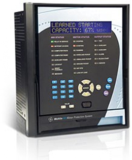 These units are becoming more and more sophisticated, providing a wealth of valuable data and protection for the motor. They also provide a number of circuit parameter settings that can shut the motor down. These safeguards are all derived from the voltage and current inputs, that being the PT and CT outputs. What if you develop a slight CT or PT anomaly?
Never make an immediate determination that the fault is related to the motor. It could be a motor or secondary circuit problem.
Potential transformer faults are generally easier to identify. With most applications, one set of PT’s will feed secondary voltage to multiple units. In this configuration it is quite simple to identify PT related issues. If the problem is common to all units fed from the PT’s it is most likely PT related. To be certain, the voltage source upstream of the PT’s should be checked to make sure it doesn’t exhibit similar problems. With “stand alone units,” look for similar anomalies in the current. If you have unbalanced voltage, for example, that will affect the current. Again, check the power source up stream and make sure the supply voltage is good.

CT’s are a different story. Each unit will, generally have CT’s at the motor starter directly off the output. Current unbalance is a common parameter that is programmed to shut down the affected motor. The best way to test CT’s is with the unit de-energized. Refer to wiring diagrams and schematics and find the CT terminals in the starter. Disconnect the leads from the terminals and if necessary, configure the CT input leads in “wye” or “series” configuration. Perform resistance and inductance measurements across each set of CT windings, 1-2, 1-3 and 2-3. (Note digital multimeter readings for resistance are not sufficient) Resistance values may appear slightly unbalanced or maybe normal. The inductance measurement is what will provide the best indication of CT condition. A moderate inductance unbalance may be all that is necessary to shut a motor down on current unbalance. Also using a low voltage, the CT’s may be tested to ground.

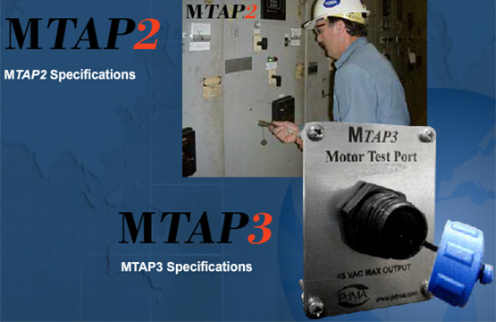
Low voltage < 1000V applications are much easier to check. If a PT or CT problem is suspected, simply connect on the primary circuitry and test from there. If no problem is identified, the CT’s or PT’s are at fault. If you have comparable readings to what was noted on the secondary, then the problem is in the motor or motor circuit.
Secondary testing is means of routine monitoring of critical motors. When done properly and with the understanding that the secondary circuitry may have problems, it can be reliable and effective method for evaluating motor and motor circuit condition.